This tutorial will explain how to setup VMware NSX. NSX 6.4.0 was used for this tutorial, other NSX versions follow the same setup but you may notice some differences as you go along.
1) Deploy the NSX Manager OVA using vCenter (it doesn’t have to be deployed in the same vCenter you will be using it in).
- Select the relevant Cluster, VM Folder, Storage & Network (for management of NSX Manager) settings in the OVA wizard
- The “Customize template” step will require relevant required info to be input such as Hostname, IP, DNS, NTP & Password for the NSX Manager
2) Once deployed open the NSX Manager web page (FQDN of appliance) to configure vCenter relationship
- Username is admin and the password is the password you specified in step 1 above
- NSX Manager and vCenter have a 1:1 relationship
- Use the vCenter Server that has the vDS and VMs you want to benefit from NSX
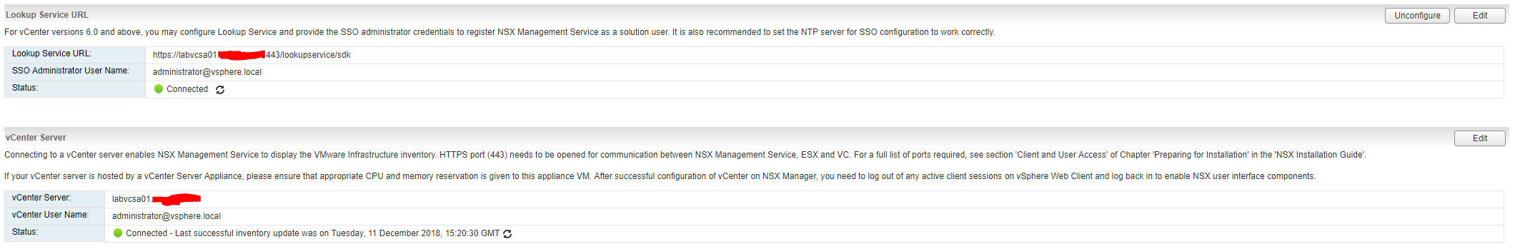
- The “Lookup Service URL” should be configured: https://{vCenter_FQDN}:443/lookupservice/sdk E.G. https://vc01.company.net:443/lookupservice/sdk
- The “vCenter Server” should be configured: {vCenter_FQDN} E.G. vc01.company.net
- Both the “Lookup Service URL” & “vCenter Server” should authenticate with the [email protected] credentials
- Once done the NSX Manager vCenter connection should look like below:
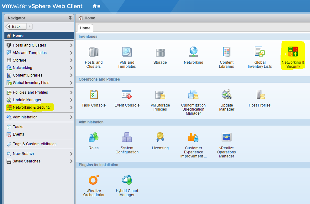
3) Login to vCenter with [email protected] credentials
- You will now see the “Networking & Security” menu option like below:
4) Configure NSX user permissions
- Under “System -> Users and Domains” you can add a user or group that exists in vCenter (can be local or domain user/group) and assign an NSX role
5) Build NSX Controller Cluster
- Under “Networking & Security -> Installation and Upgrade -> Management” you can add a controller node
- You need to create 3 controller nodes (ideally built on separate hosts)
- Clicking the + button brings up the below settings box:
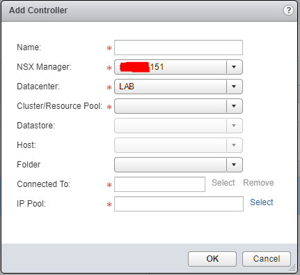
- Enter a unique friendly name & select the relevant datacenter/cluster/host/datastore
- “Connected To” should be the network you want the controllers to use to communicate, usually this is the same as the NSX Manager management network
- “IP Pool” should be a unique pool of IP addresses just for the NSX Controllers to be assigned. You can create an IP Pool when creating the first controller
- When creating the first controller you will also be asked for a password, this password will be for the controller cluster
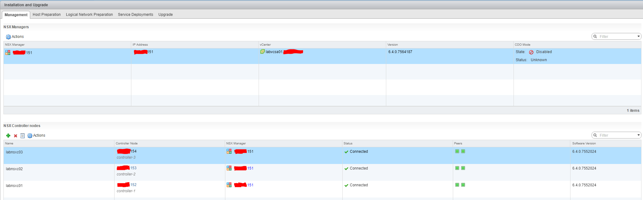
- You can only build one controller at a time so prepare yourself for some waiting 😉
- Once all 3 controllers have been built the “Management” tab should look like below:
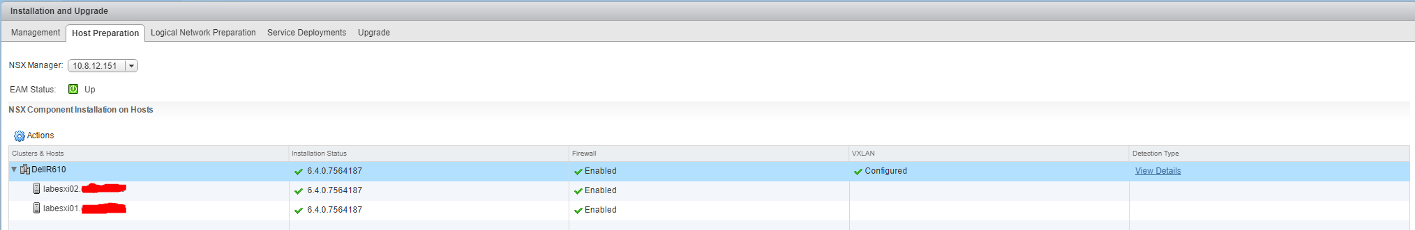
6) Prepare Clusters & Hosts for NSX
- Under “Networking & Security -> Installation and Upgrade -> Host Preparation” select the cluster (rather than a host) you want to enable for NSX and click “Install”
- The vSphere hosts do NOT need to be in Maintenance mode for this installation
- During this installation the vSphere hosts will have the NSX VIBs installed to handle VXLAN (Virtual Extensible LAN), DLR (Distributed Logical Router) and DFW (Distributed Firewall)
- Once complete the “Installation Status” will change to show the NSX version installed and “Firewall” will have status “Enabled”
- Click “Configure” under “VXLAN” (Virtual Extensible LAN)
- Select the required vDS (Virtual Distributed Switch), enter the VLAN ID to use for VXLAN VMkernel interface and set MTU to 1600
- “VMKNic IP Addressing” should use a unique pool of IP addresses for the specified VLAN ID (just like the NSX Controllers). Usually this network/VLAN is different to the NSX Manager/vSphere hosts management network(s)
- Specify the required “VMKNic Teaming Policy” and click “OK”
- During this configuration the vSphere hosts will get a new VMkernel port for VTEP (VXLAN Tunnel Endpoint)
- Once complete the “VXLAN” will change to status “Enabled”
- Once complete the “Host Preparation” tab should look like below:
7) Logical Network Preparation
- Under “Networking & Security -> Installation and Upgrade -> Logical Network Preparation” another 3 tabs will be exposed
- “VXLAN Transport”: This tab will just show the VXLAN configuration you created in previous step
- “Segment ID”: Edit to specify a range of IDs e.g. 5000-8000
- A Logical Switch (virtual wire) will use the Segment ID as the VNI (VXLAN Network Identifier). Therefore you must specify enough IDs for the Logical Switches you want to be able to create
- “Transport Zones”: Create a transport zone for Logical Switches (virtual wires) to be part of
- A Transport Zone defines which clusters of hosts will be able to see and use the Logical Switches within the zone
- When creating a Transport Zone specify a name, optional description and clusters to be part of the zone. Specify “Unicast” for “Replication Mode” to make the NSX Controllers responsible for replication
That concludes the “Setup” for NSX. The next jobs are to create NSX Edges – both ESGs (Edge Services Gateways) and DLRs (Distributed Logical Routers), Logical Switches (virtual wires) and DFW (Distributed Firewall) rules.
Be First to Comment